Time-Circuits-Display
DIY additions for the Time Circuits Display
Speedometer
Despite CircuitSetup offering a really good and screen-accurate Speedo, you might want to make your own.
 |
|---|
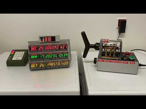
| Click to watch the video |
The speedo display shown in this video is based on a fairly well-designed stand-alone replica I purchased on ebay. I removed the electronics inside and wired the LED segments to an Adafruit i2c backpack (from the Adafruit 878 product) and connected it to the TCD. Yes, it is really that simple.
What you need is a box, the LED segment displays and a HT16K33-based PCB that allows accessing the LED displays via i2c (address 0x70). There are various readily available LED segment displays with suitable i2c break-outs from Adafruit and Seeed (Grove) that can be used as a basis:
The product numbers vary with color, the numbers here are the red ones.
For wiring information, please see here.
Software setup
The type of display needs to be configured in the Config Portal’s Speedo display type drop-down widget.
For DIY speedos, there are two special options in the Speedo Display Type drop-down: Ada 1911 (left tube) and Ada 878 (left tube). These two can be used if you connect only one 2-digit-tube to the respective Adafruit i2c backpack, as I did in case of my speedo replica as well as my Wall Clock.
GPS receiver
The CircuitSetup original speedo has a built-in GPS receiver, but the firmware also supports alternatives such as the
or any other MT(K)3333-based GPS receiver, connected through i2c (address 0x10). Note that the supply and bus voltage must be 5V.
The GPS receiver can be used as a source of authoritative time (like NTP) and speed of movement.
For wiring information, see here.
Rotary Encoder
A rotary encoder is, simply put, a turnable knob. On the TCD, rotary encoders can be used for speed and/or audio volume.
The firmware currently supports the
i2c rotary encoders. For the Adafruit and the DuPPa, I recommend buying the PCBs without an actual encoder and soldering on a Bourns PEC11R-42xxy-S0024.
Up to two rotary encoders can be connected, one for speed, one for volume.
Hardware Configuration
In order to use an encoder for speed or volume, it needs to be configured as follows:
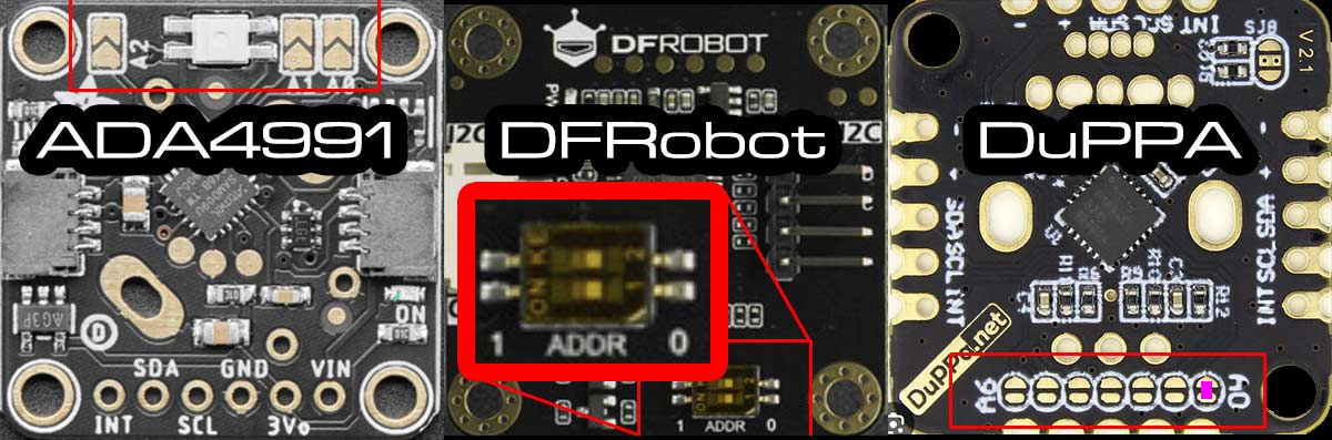
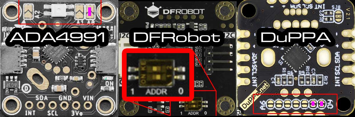
| Ada4991 | DFRobot | DuPPA | |
| Speed | Default | SW1=0,SW2=0 | A0 closed |
| Volume | A0 closed | SW1=0,SW2=1 | A0,A1 closed |
For DuPPA: RGB-encoders not supported.
Here is how they look configured for speed (the purple spots are solder joints):
Here is the configuration for volume:
For wiring information, see here.
Temperature/humidity sensor
The firmware supports connecting a temperature/humidity sensor for “room condition mode” and for displaying ambient temperature on a speedo display while idle.
 |
|---|
| RC mode |
The following sensor types are supported:
- MCP9808 (address 0x18 - non-default),
- BMx280 (0x77),
- SI7021,
- SHT40 (0x44),
- SHT45 (0x44),
- TMP117 (0x49),
- AHT20/AM2315C,
- HTU31D (0x41 - non-default),
- MS8607
- HDC302x (0x45 - non-default)
The BMP280 (unlike BME280), MCP9808 and TMP117 work as pure temperature sensors, the others for temperature and humidity.
All of those are readily available on breakout boards from Adafruit or Seeed (Grove); the links in above list lead to tested example products. Only one temperature/humidity sensor can be used at the same time.
For wiring information, see here.
Note: You cannot connect the sensor chip directly to the TCD control board; most sensors need at least a voltage converter/level-shifter. It is recommended to use Adafruit or Seeed breakouts, which all allow connecting named sensors to the 5V the TCD board operates on.
Light sensor
The firmware supports connecting a light sensor for night-mode switching.
The following sensor types/models are supported:
- TSL2591,
- TSL2651,
- BH1750,
- VEML7700,
- VEML6030 [0x48 - non-default],
- LTR303/LTR329
The VEML7700 can only be connected if no CircuitSetup Speedo or third-party GPS receiver is connected at the same time; the VEML6030 needs its address to be set to 0x48 if a CircuitSetup Speedo or third party GPS receiver is present at the same time.
Almost all these sensor types are readily available on breakout boards from Adafruit or Seeed (Grove); the links in above list lead to tested example products.
For wiring information, see here.
Note: You cannot connect the sensor chip directly to the TCD control board; most sensors need at least a voltage converter/level-shifter. It is recommended to use Adafruit or Seeed breakouts, which all allow connecting named sensors to the 5V the TCD board operates on.
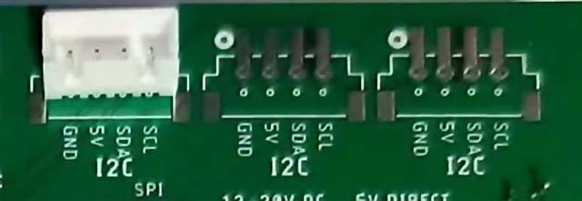
I2C peripheral wiring
All i2c peripherals described above are to be wired as follows:
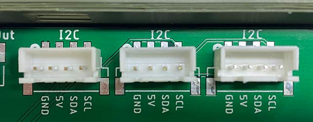
On the TCD control board, there are three breakouts named “I2C”, at least one of which has a header soldered on; it does not matter which one you use to connect your sensors/speedo/GPS/rotary encoders. On Control Boards version 4, there are screw terminals for the other two i2c connectors; for older boards, I recommend to solder on XH 4-pin headers to the other two i2c breakouts as well (like in the second picture). When you order a CircuitSetup Speedo, they will include such headers if you request them. Do not solder wires directly to the board!
On most peripherals the pins are named as follows, and need to be connected to the corresponding pins on the control board:
| Peripheral PCB | TCD control board |
| GND or "-" | GND |
| VIN or 5V or "+"</a> | 5V |
| SDA (SDI on BME280) |
SDA |
| SCL (SCK on BME280) |
SCL |
For longer cables, ie >50cm (>20in), I recommend using a twisted pair cable, and to connect it as follows:
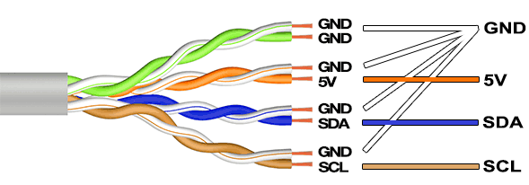
Important: The TCD control board delivers and drives the i2c bus on 5V. Most sensors/GPS receivers operate on 3.3V. Therefore, you cannot connect the chips directly to the TCD control board without a level-shifter. This goes for the power supply as well as the i2c bus signals (SDA, SCL). I only use readily available sensor breakout boards that include level-shifters.
Multiple i2c devices
If going by the book, multiple i2c devices should be daisy chained; however, I had sensors, speedo and GPS receivers run in parallel without issues for months.
Note that you can only use one per device type (temperature/humidity sensor, light sensor, GPS receiver, Speedo display) at a time. As regards rotary encoders, one for speed and one for volume can be connected.
To avoid running out of i2c connectors, and to reduce the cable chaos, I designed a small PCB that acts as a i2c and power splitter:


- 12V in: 12V input for the TCD and the TFC switch, using a 5.5/2.1mm standard DC power plug.
- Input from TCD: Connect those to the TCD control board as indicated above
- 12V output: 12V power for the TCD
- four i2c screw connctors for sensors, rotary encoders, Speedo, etc
- TFC drive switch connector
Production files are in the splitter folder.
i2c addresses
i2c devices have “addresses”. Most sensors either only support one i2c address, or are recognized by the firmware (only) by their default address. For those, nothing must be done in order to use them with the Time Circuits Display.
Notable exceptions are the TMP117 and HTU31D sensors: Their address needs to changed in order to be recognized by the firmware. On the Adafruit breakouts, this is done by connecting two solder pads on the back side of the PCB:

This image shows the HTU31D PCB’s back side. Connect (shorten) those two pads in order to change the address. It looks similar on the TMP117.
For Rotary Encoders, see here.
Other props
Connecting props by wire
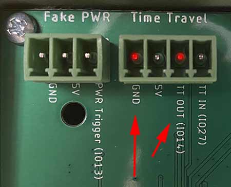
The TCD can tell other props about a time travel. It does so by setting a pin (IO14, labeled “TT OUT” on Control Boards 1.3 and later) to high or low. “High” is between 2.7V and 3.3V.
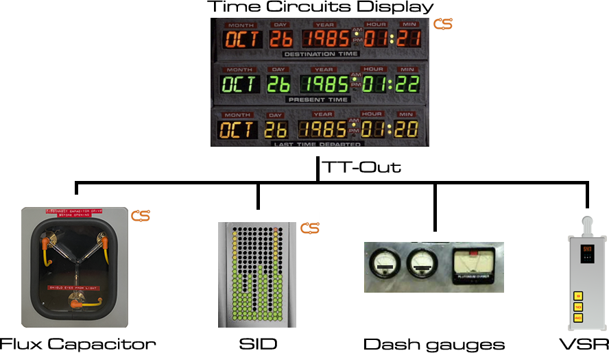
You need two wires for connecting the TCD: TT_OUT (IO14) and GND, which need to be connected to the respective pins of the prop.
 |
|---|
| TT_OUT/IO14 on board version 1.3 |
 |
|---|
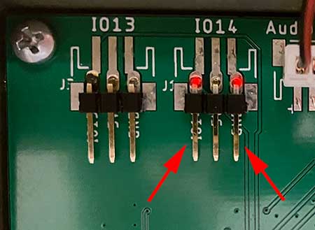
| IO14 on board version 1.2 |
Here’s the timing diagram:
1) Option Signal Time Travel without 5s lead unchecked
|<---------- speedo acceleration --------->|                         |<-speedo de-acceleration->|
0....10....20....................xx....87..88------------------------88...87....................0
                                           |<--Actual Time Travel -->|
                                           |  (Display disruption)   |
                                      TT starts                      Reentry phase
                                           |                         |
             |<---------ETTO lead--------->|                         |
             |                                                       |
             |                                                       |
             |                                                       |
    TT-OUT/IO14: LOW->HIGH                                  TT-OUT/IO14: HIGH->LOW
“ETTO lead”, ie the lead time between TT_OUT/IO14 going high and the actual start of a time travel is defined as 5000ms (ETTO_LEAD_TIME). In this window of time, the prop can play its pre-time-travel (warm-up/acceleration/etc) sequence. The sequence inside the time “tunnel” follows after that lead time, and when IO14 goes LOW, the re-entry into the destination time takes place.
2) Option Signal Time Travel without 5s lead checked
|<---------- speedo acceleration --------->|                         |<-speedo de-acceleration->|
0....10....20....................xx....87..88------------------------88...87....................0
                                           |<--Actual Time Travel -->|
                                           |  (Display disruption)   |
                                      TT starts                      Reentry phase
                                           |                         |
                                           |                         |
                                           |                         |
                                           |                         |
                                           |                         |
                                  TT-OUT/IO14: LOW->HIGH    TT-OUT/IO14: HIGH->LOW
In this case, there is no lead. The time travel starts immediately.
Text & images: (C) Thomas Winischhofer (“A10001986”). See LICENSE. Source: https://tcd.out-a-ti.me